Parallel circuits : the nature of parallel circuits, five methods of computation and power dissipation in parallel circuits
Parallel Circuits
11–1 THE NATURE OF PARALLEL CIRCUITS
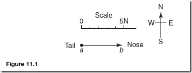
You should recall that series circuits were defined as having one, and only one, path along which the current can flow. By contrast, a parallel circuit has more than one path through which the current can flow. Figure 11–1 is such a parallel circuit. This is the standard representation where all resistors are drawn parallel to one another, resembling the ties between railroad tracks.
Now look at the two schematics in Figure 11–2, which are representations of the same parallel circuit shown in Figure 11–1. The common feature of these parallel circuits can be detected by carefully tracing each possible current path. Then it will become clear that each individual resistor is connected to the negative and positive pole of the battery. If you have difficulty in perceiving this fact, trace the negative and positive supply lines with two different-colored pencils from the source to each resistor.


What all these drawings convey is the fact that there is only one voltage serving all load resistors. (Compare this with the characteristics of a series circuit, where every resistor may have a different voltage drop.) Mathematically stated,
Also, as you trace the current path from its power source, you will notice that the current divides at some junction point, flows through the individual branch resistors, and then recombines at some other junction point before it returns to the power source.
Now, carefully check the three drawings just mentioned. They all show identical current flow to demonstrate that the total line current (supplied by the source) is equal to the sum of all the individual branch currents. (Compare this with the characteristics of a series circuit, where we dealt with one common current in each part of the circuit.) Mathematically stated,
We have compared the voltage and current distribution of parallel circuits with that of series circuits. Now it is time to compare the total resistance of such circuits.
In a series circuit, as you should recall, the total resistance increases with every additional resistance. In parallel circuits, by contrast, we encounter exactly the opposite.
In other words, the total resistance of a parallel circuit decreases whenever additional resistors are connected to the circuit. In fact, the total resistance is always smaller than any of the individual branch resistors.
There are five different methods by which the total resistance of a parallel circuit may be computed. How to employ these methods will be the subject of the next few sections.
11–2 FIVE METHODS OF COMPUTATION
Method #1: Use of Ohm’s Law for Computing RT
An easy way of determining the total resistance is by applying Ohm’s law:
This necessitates, in some cases, finding the total current first. The following example should make this clear.
EXAMPLE 11–1
Given: The circuit shown in Figure 11–3.
Find:


With the number 0.3667 in your calculator display, press 1/X again and obtain the answer: 2.73. The series of keys to press on a scientific calculator to determine the correct answer is shown in Figure 11–5.
Method #3: A Practical Method
The reciprocal equation inevitably requires the finding of the lowest common denominator. This procedure could, at times, be cumbersome. The following method is offered as an alternative practical solution. This method works in all cases.
EXAMPLE 11–3
Given: The circuit shown in Figure 11–6.
Find: The total resistance.
Solution
Pick the largest resistance value in the circuit; then divide it by all the parallel resistors (including itself).


Now that you have been given an example, try to do it yourself. Substitute the numbers 20, 30, and 60 for the resistance values shown in Figure 11–6. When you are done, you should get 10 ohms for an answer. If not, better try again.
Method #4: The Product Over the Sum Formula
This is a quick way of getting the answer, provided that only two resistors are given. Study the example shown here. The equation to be used is
EXAMPLE 11–4
Given: The circuit shown in Figure 11–7.
Find: The total circuit resistance.


Solve the above problem once again, substituting 15 ohms for R1 and 30 ohms for R2. Your answer should be 10 ohms.
Method #5: A Special Condition: All Equal Resistors
Occasionally, you may encounter circuits where all load resistors are of identical value. That makes our computation really easy. We merely take the resistance value of one device and divide it by the number of branch resistors. Mathematically, we might state it like this:

What answers did you get for the circuits shown in D and E? Do you agree with 12 and 10 ohms, respectively?
As with series circuits, there are three rules, when used with Ohm’s law, that can be applied in solving for unknown electrical quantities in parallel circuits.

1. Voltage is the same across all branches of a parallel circuit. (Voltage remains the same.)
2. The total current is the sum of the currents through individual branches. (Current adds.)
3. The reciprocal of the total resistance is equal to the sum of the reciprocals of the resistance of each branch.

11–3 POWER DISSIPATION IN PARALLEL CIRCUITS
Each resistor develops heat in accordance with the amount of current flowing through it. Regardless of the type of circuit involved, the power dissipated by R1 is P1 5 E1I1. Likewise, P2 5 E2I2; P3 5 E3I3, and so on.
The total circuit power (PT) is simply the sum of all the various power dissipations on the branch resistors. Mathematically stated,
PT 5 P1 1 P2 1 P3 1 . . . 1 Pn
Of course, if the total current is known, it is even simpler to compute PT directly by using the power equation PT 5 ET IT or PT 5 (IT)2 RT.
EXAMPLE 11–6
Given: The circuit shown in Figure 11–9.
Find: The total power consumption.