Useful Applications of atmospheric and liquid pressure
1- The common pump - lift pump-
Pumps were used successfully to raise water from wells long before their action were properly understood, and are still to be seen in country villages, carefully preserved as relics of the past.
Common pump diagram: 
They consist of a cylindrical metal barrel with a side tube near the top to act as a spout.
At the bottom of the barrel, where it joins a pipe leading to the well, there is a clack valve B. The latter is a hinged circular leather flap weighted by a brass disc so that it normally falls shut.
A plunger carrying a leather cup and fitted with a second clack valve A is moved up and down inside the barrel by a handle H.
How it works
To start the pump working it is first primed by pouring some water on the top of the plunger.
This makes a good air seal and prevents leakage of air past the plunger during the first few strokes which are needed to fill the pump with water. Once the pump is filled the action is as follows:
The down stroke
When the plunger moves downwards the valve B closes under its own weight. At some time water inside the pump passes upwards through the valve A into the space above the plunger.
The upstroke
On the upstroke the valve A closes by its own weight, and as the plunger rises, water is pushed up the pipe through the valve B by atmospheric pressure acting on the surface of the water in the well.
At the same time, the water above the plunger is raised and flows out of the spout.
Limitations of the common pump
Owing to the fact that atmospheric pressure cannot support a column of water more than about 10 m long, it follows that 10 m is the theoretical maximum height to which water can be raised by a common pump.
An imperfect vacuum, however, is usually obtained owing to bubbles from dissolved air forming near the top of the water column.For this reason the practical working height of a pump is rather less than 10 m.
Occasionally one finds a pump which can lift water to a height greater than the theoretical maximum. This will occur if air can leak into the pipe near the bottom. Air bubbles then rise in the pipe and break up the water column into a series of shorter columns. Thus, although the total length of water in the pipe is not more than about 10 m, the total length of water plus air is greater than 10 m. Consequently, water can enter the pump.
A similar thing can happen when one is using a pipette. If the pipette is inadvertently lifted out of the liquid while it is being filled air will enter and the bubbles will carry the liquid up into the mouth almost immediately.
2-The force pump
For raising water to a height of more than 10 m, the force pump is used. It consists of a pump with a solid plunger and foot valve B, connected by a pipe to a chamber C through a valve A.The upstroke
On the upstroke valve A closes and the atmospheric pressure pushes water up into the pump through valve B.The down stroke
On the down stroke, valve B closes and water is forced into the chamber C through valve A by the pressure due to mechanical force exerted on the plunger.Force pump diagram diagram: 
The exit pipe p projects into the chamber C so that some air becomes trapped at the top of the chamber. This is compressed and acts as a cushion, thus preventing a sudden jolt to the pump when the water column in P falls slightly and sharply closes valve A at the beginning of the upstroke. C also helps to expel water on the upstroke.
The maximum height to which water may be raised by this means depends on:
(a) The force which is exerted on the plunger during the down stroke.
(b) The ability of the pump and its working parts to withstand the pressure of the long column of the water in the exit pipe P.
3- Early fire pumps
Towards the end of the eighteenth century manual fire pumps came into use which consisted of a pair of force pumps connected to a long handle and worked by a team of four men.
Both pumps fed alternately into a chamber with a compressed air space similar to that described above. At the moment of change-over of feed from one pump to the other the compressed air expanded, and so maintained a steady flow of water to the hoses.
4- The preserving jar and atmospheric pressure
Atmospheric pressure is used in the kitchen in connection with preservation of fruit.
Preserving jar in the kitchen: 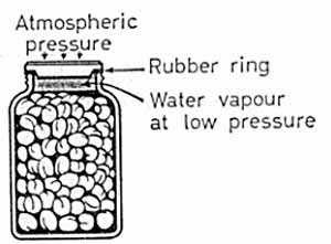
The preserving jar, with which we are familiar, is a glass jar covered with a glass cap seated on a flat rubber ring.
Clean fruit and water are placed in the jar, leaving a small air space at the top. Several of these jars are placed in a large vessel of cold water, which is then slowly brought to the boil. During this process the glass caps with their rubber rings are loosely held in position by a metal screw cap.
About 10 minutes' boiling is generally sufficient to sterilize the fruit and to cause air to be driven from the jars by steam from the water inside. The screw caps are then tightened and the jars removed from the water.
After cooling, the space at the top of the jars contains only water vapor at low pressure. As a result, the glass cap is then firmly pressed down by atmospheric pressure. No bacteria-laden air can afterwards enter, and so the contents remain in good condition for a long period.
It is important to notice that, when the jars have cooled the presence of the metal cap is not strictly necessary, as the seal is now maintained by atmospheric pressure.
5- The siphon: 2 explanations
Most people are familiar with the use of a siphon for removing water from fish aquaria or other receptacles which cannot otherwise be emptied conveniently.
Siphon diagram: 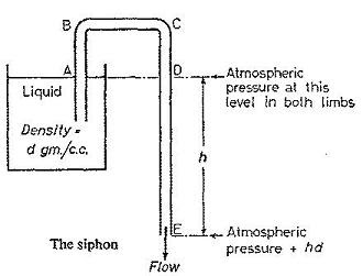
The siphon is a bent tube made of glass, rubber or plastic tubing with its short arm dipping into the tank of a liquid and its longer arm outside.
To start the siphon it must first be filled with liquid. After this the liquid will continue to run out so long as the end E is below the level of the liquid in the tank.
At one time it was generally accepted that a siphon worked by atmospheric pressure. But there is now strong evidence to support the view that cohesion between the liquid molecules plays an important part.
Older explanation
The pressures at A and D in the two limps of the tube are both equal to atmospheric pressure, since they are at the same horizontal level as the surface of the liquid in the tank. The pressure at the outlet E is equal to atmospheric pressure plus the pressure hρg due to the column DE. The excess pressure, hρg, therefore causes the liquid to flow out of the tube at E.
Also, since the liquid has to rise a distance AB up the tube, it follows that the siphon will fail to work if AB is greater than the barometric height appropriate to the liquid being used.
Newer explanation
Experiment shows that siphons can be made to work in a vacuum and that, in certain cases, the flow will continue even if AB is somewhat greater than the appropriate barometric height.
The presence of atmospheric pressure, therefore, does not appear to be essential. It would seem that the flow of liquid occurs owing to the greater weight of the column CE, which pulls the shorter column AB through the cohesion ( attractive force ) of the liquid molecules. The action can be likened to that of a chain passing over a freely running pulley which will run off in the direction of the longer side.
Critical comment
Only pure liquids will siphon satisfactory in a vacuum. If dissolved gases are present the cohesive force between the molecules is greatly lowered and bubbles readily form under reduced pressure. Hence, atmospheric pressure is a necessary condition in the case of impure liquids as it compresses the liquids in the tubes and prevents breakage of the liquid columns through the formation of bubbles from dissolved gases.
Did I forget to mention some applications of atmospheric and liquid pressure? Of course I did :). So, if you - my dear reader- can add some applications, you are welcome!. Thanks for visiting and I hope you come back soon.


