Strength of materials. Elasticity and Hooke’s law
Before various materials are used in the construction of machinery and buildings, tests are accomplished to ensure that they are able safely to stand up to the stresses to which they are likely to be subjected.
Industrial laboratories have special apparatus for carrying out these tests.
Brittle substances such as masonry and cast iron will support large weights or forces of compression, but will easily break if stretching ‘tensile’ forces are applied.
Where tensile forces are involved an elastic material such as steel is used.
It is advisable to place a bucket of sand or some soft material beneath the apparatus to check the fall of the weights when the wire breaks at a load of about 4 N.
Industrial laboratories have special apparatus for carrying out these tests.
Brittle substances such as masonry and cast iron will support large weights or forces of compression, but will easily break if stretching ‘tensile’ forces are applied.
Where tensile forces are involved an elastic material such as steel is used.
Definition of Elasticity:
Elasticity is the ability of a substance to recover its original shape and size after distortion.
Robert Hooke’s law
During the time London was being rebuilt after the great fire of 1666 a great deal of research went on in connection with building construction and the strength of materials.
Robert Hooke, who was Chief Surveyor to the City of London, took a leading part in this work and extended his researches to include an investigation of elasticity in general.
He came to the conclusion that,
Robert Hooke, who was Chief Surveyor to the City of London, took a leading part in this work and extended his researches to include an investigation of elasticity in general.
He came to the conclusion that,
provided the elastic limit is not exceeded, the deformation of a material is proportional to the force applied to it. This statement is known as Hooke’s law.
The equation is:
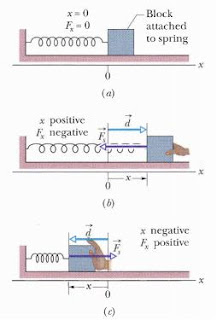
F = - k x as you can see in the image.
When x is positive ‘the spring is stretched to the right on the x axis’, then F is negative ‘it is a pull toward the left’.
When x is negative ‘the spring is compressed to the left’, then F is positive ‘it is a push toward the right’.
When x is positive ‘the spring is stretched to the right on the x axis’, then F is negative ‘it is a pull toward the left’.
When x is negative ‘the spring is compressed to the left’, then F is positive ‘it is a push toward the right’.
 |
| Hooke's law |
Hooke illustrated the law by reference to four different experiments:
1- Loading a wire ‘deformation = increase in length’
2- Loading a spiral spring ‘ deformation = increase in length’. Briefly, when a spring is fixed at one end and a force is applied to the other, the extension of the spring is proportional to the applied force, provided the force is not large enough to stretch the spring permanently.
3- Loading a horizontal beam fixed at one end ‘deformation = depression of the free end’.
4- Tightening a watch spring ‘deformation = angular rotation’.
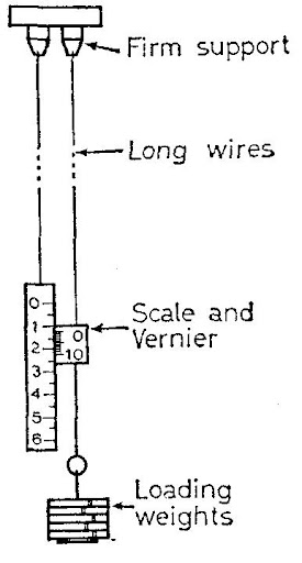
Experiment to study the relation between load and extension for a copper wire
Two copper wires about 50 cm long and 0.45 mm diameter are used in this experiment.
One, the test wire, carries a vernier and the other a millimeter scale about 15 cm long.
The two wires are held by chucks mounted on a rigid wall bracket and hang vertically as shown in the image.
Two wires are used to eliminate temperature errors:
Thermal expansion affects both wires equally, and therefore no relative change in length occurs.
The object of the experiment is to study the increase in length of the test wire as it is gradually loaded.
An initial load is hung from the wire in order to pull it straight and the vernier reading noted. Further readings are obtained as the wire is loaded by, say, 0.25 Newton at a time. The results are entered in a suitable table and a graph plotted of load against extension.
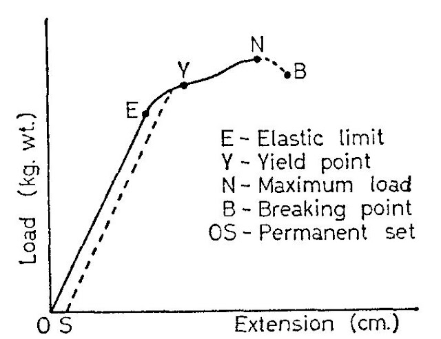 |
| Load/extension graph |
At the point Y, called the yield point, the wire ‘runs’ and a given increase in load produces a much bigger extension than previously.
Internal slipping is now taking place between the layers of atoms in the metal crystals. This is described as plastic deformation. It leads to an alteration in the grouping of the crystals ‘metallurgists call this, grain flow’.
More importantly, it is accompanied by an increase in the strength of the metal. Metal or alloys which undergo plastic deformation are said to be ductile.
The point N represents the maximum load the wire can stand. The force per unit area of cross-section for this loading is called the ultimate tensile stress of the material. At this stage the wire is liable to stretch suddenly and form a waist at its weakest part. Once this happens, the wire will go on stretching, even under reduced load, until the breaking point, B, is reached.
Interpretation of the load/extension graph
The first portion, OE, of the graph is a straight line showing that the extension is proportional to the load. The wire stretches in accordance with Hooke’s law. Over this range the wire is perfectly elastic, i.e., it will recover its original length when the load is removed.
This may be explained as follows.
This may be explained as follows.
We learned that the molecules of a solid are continuously oscillating about their equilibrium positions.
In the case of an elastically stretched wire the molecules are pulled slightly apart so that they now oscillate about a mean position where the net force is attractive.
These attractive forces give resultant attractions at the ends of the wire which are balanced by the externally applied forces.
In the case of an elastically stretched wire the molecules are pulled slightly apart so that they now oscillate about a mean position where the net force is attractive.
These attractive forces give resultant attractions at the ends of the wire which are balanced by the externally applied forces.
The force per unit area of cross-section of the wire corresponding to the point E is called the elastic limit of the material. For loads beyond this, the graph bends slightly; Hooke’s law ceases to apply and the wire beings to stretch permanently.
If it is unloaded during this stage the wire will not return to its original length but will be found to have acquired a permanent set which is measured by the distance OS along the extension axis.
If it is unloaded during this stage the wire will not return to its original length but will be found to have acquired a permanent set which is measured by the distance OS along the extension axis.
Automatic plotting of the load/extension graph
Owing to the necessity to reduce the load when a waist occurs the simple apparatus used in the above experiment cannot be used to obtain readings for the portion NB of the graph.
The complete graph can, however, be plotted automatically in a few minutes using the apparatus ‘ not shown in the image, sorry!’ which is suitable for testing wires about 0.5 mm or less in diameter.
A 50 cm length of wire to be tested is clamped, one end to a strong spring, and the other end to a nut on a long screwed rod. Turning the handle of the screw, tensions and stretches the wire.
The extension of the previously calibrated spring gives a measure of the load applied and this is transmitted by a string passing round a pulley to the load cross-slide.
A light beam at right angles to the cross-slide carries a sliding ball-point pen. Simultaneously, a string passing round pulleys as shown conveys a movement exactly equal to the extension of the test wire to the extension cross-slide.
This carries a beam at right angles to it which pushes the pen along the first beam.
The pen plots a graph of load against extension on a sheet of graph paper beneath.
In this way the characteristics of a number of different materials may be compared on the same graph paper, using pens of different colors.
Industrial applications of metallurgical studies
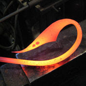
The behavior of metals and alloys under stress is important in connection with the forging of metal components.
In this process the hot or cold metal is squeezed or hammered into shape instead of being cast in a mold.
 |
| Metallurgi |
In this process the hot or cold metal is squeezed or hammered into shape instead of being cast in a mold.
 |
| forged-shape |
The image shows the crystal grain flow which takes place during a forging operation. In this condition the material becomes much tougher and more resistant to the formation of cracks which would lead to ultimate fracture.
Examination of the crystal structure and behavior of materials has led to the development of tough alloys so vital to human safety as, for example, in aircraft construction.
Bottom line: I hope that article was informative. If you like it you may save it as pdf here : Hooke's law