Posts

Showing posts with the label ALTERNATING CURRENT GENERATORS

Capacitors and RC Time Constants : Dielectric characteristics , Capacitance formulas and Capacitors in parallel.
Image
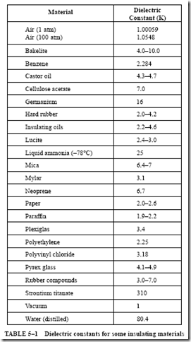
DIELECTRIC CHARACTERISTICS Three factors were shown to affect the capacitance of a capacitor. One factor is the type of insulating material used for the dielectric. Most capacitors are constructed using a dielectric material having a higher dielectric constant than air. The dielectric constant of an insulating material measures the effectiveness of the material when it is used as the dielectric of a capacitor. It is assumed that air has a dielectric constant of one. If a two-plate capacitor has a dielectric consisting of paper impregnated with paraffin, rather than a dielectric of air, the capacitance will increase. If the capacitance is doubled when using paper in place of air for the dielectric, the dielectric constant for paper is 2. This value indicates the degree of distortion of the electron orbits in the dielectric for a given applied voltage. Table 5–1 lists the dielectric constants of some insulating materials. Dielectric Strength If the voltage across the plates o...

Capacitors and RC Time Constants : Capacitors in series , Capacitors in network systems , Energy in a capacitor and RC time constants.

Image
CAPACITORS IN SERIES When capacitors are connected in series, the dielectrics of the individual capacitors are connected one after the other to form a single circuit path. This arrangement is equivalent to increasing the thickness of the dielectric of one capacitor. This means that the total capacitance of the circuit is less than the capacitance of any individual capacitor. When capacitors are charged in a series circuit, the same number of electrons flow to each capacitor. As a result, each capacitor has the same charge (Q) in coulombs. For example, Figure 5–9 shows three capacitors connected in series across a line volt- age (V). The capacitors have the same ratings as in Figure 5–8 for a parallel circuit. It can be shown that the total capacitance of the capacitors connected in series is less than the capacitance of any one capacitor. The voltage across the series circuit is The charge in coulombs on each capacitor is the same: The formulas for total capacitance can...

Principles of ac voltage control and summary of alternating current generators .

Image
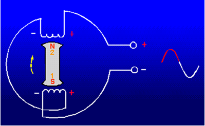
PRINCIPLES OF AC VOLTAGE CONTROL In an alternator, an alternating voltage is induced in the armature windings when magnetic fields of alternating polarity are passed across these windings. The amount of voltage induced in the windings depends mainly on three things: (1) the number of conductors in series per winding, (2) the speed (alternator rpm) at which the magnetic field cuts the winding, and (3) the strength of the magnetic field. Any of these three factors could be used to control the amount of voltage induced in the alternator windings. The number of windings, of course, is fixed when the alternator is manufactured. Also, if the output frequency is required to be of a constant value, then the speed of the rotating field must be held constant. This prevents the use of the alternator rpm as a means of controlling the voltage output. Thus, the only practical method for obtaining voltage control is to control the strength of the rotating magnetic field. The streng...

Single-phase alternators, three-phase alternator and frequency

Image
ANSWERS TO QUESTIONS Q1. THROUGH Q21. A1. A conductor and a magnetic field. A2. Armature. A3. Rotating armature and rotating field. A4. Output voltage is taken directly from the armature (not through brushes or slip rings). A5. To provide dc current for the rotating field. A6. Kilovolt-amperes (volt amperes). A7. Steam turbine. A8. Internal combustion engines, water force and electric motors. A9. One voltage (one output). A10. In series. A11. Placement of armature coils. A12. Three. A13. C is 1.414 times greater than A or B. A14. Each phase is displaced 120° from the other two. A15. Wye and Delta. A16. Three single-phase, delta-delta, step-down transformers. A17. Speed of rotation and number of poles. A18. 120 Hz. A19. Voltage regulation. As a percentage. A20. By varying the voltage applied to the field windings. A21. Output voltage, frequency, and phase relationships. Back Home ...