Posts

Showing posts with the label TRANSFORMERS

Summary of transformer
Image
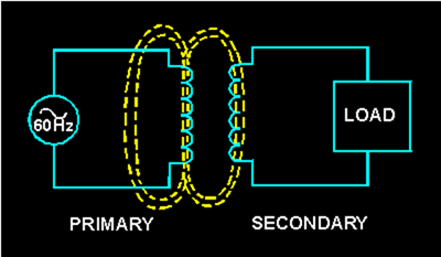
Summary of transformer As a study aid and for future reference, the important points of this chapter have been summarized below. BASIC TRANSFORMER - The basic transformer is an electrical device that transfers alternating-current energy from one circuit to another circuit by magnetic coupling of the primary and secondary windings of the transformer. This is accomplished through mutual inductance (M). The coefficient of coupling (K) of a transformer is dependent upon the size and shape of the coils, their relative positions, and the characteristic of the core between the two coils. An ideal transformer is one where all the magnetic lines of flux produced by the primary cut the entire secondary. The higher the K of the transformer, the higher is the transfer of the energy. The voltage applied to the primary winding causes current to flow in the primary. This current generates a magnetic field, generating a counter emf (cemf) which has the opposite phase to that o...

Transformer ratings and Safety effects of current on the body

Image
TRANSFORMER RATINGS When a transformer is to be used in a circuit, more than just the turns ratio must be considered. The voltage, current, and power-handling capabilities of the primary and secondary windings must also be considered. The maximum voltage that can safely be applied to any winding is determined by the type and thickness of the insulation used. When a better (and thicker) insulation is used between the windings, a higher maximum voltage can be applied to the windings. The maximum current that can be carried by a transformer winding is determined by the diameter of the wire used for the winding. If current is excessive in a winding, a higher than ordinary amount of power will be dissipated by the winding in the form of heat. This heat may be sufficiently high to cause the insulation around the wire to break down. If this happens, the transformer may be permanently damaged. The power-handling capacity of a transformer is dependent upon its ability to...

Effect of a load and Power relationship between primary and secondary windings

Image
EFFECT OF A LOAD When a load device is connected across the secondary winding of a transformer, current flows through the secondary and the load. The magnetic field produced by the current in the secondary interacts with the magnetic field produced by the current in the primary. This interaction results from the mutual inductance between the primary and secondary windings. MUTUAL FLUX The total flux in the core of the transformer is common to both the primary and secondary windings. It is also the means by which energy is transferred from the primary winding to the secondary winding. Since this flux links both windings, it is called MUTUAL FLUX. The inductance which produces this flux is also common to both windings and is called mutual inductance. Figure 5-11 shows the flux produced by the currents in the primary and secondary windings of a transformer when source current is flowing in the primary winding. Figure 5-11. - Simple transformer indicati...

COEFFICIENT OF COUPLING

Image
COEFFICIENT OF COUPLING The COEFFICIENT OF COUPLING of a transformer is dependent on the portion of the total flux lines that cuts both primary and secondary windings. Ideally, all the flux lines generated by the primary should cut the secondary, and all the lines of the flux generated by the secondary should cut the primary. The coefficient of coupling would then be one (unity), and maximum energy would be transferred from the primary to the secondary. Practical power transformers use high-permeability silicon steel cores and close spacing between the windings to provide a high coefficient of coupling. Lines of flux generated by one winding which do not link with the other winding are called LEAKAGE FLUX. Since leakage flux generated by the primary does not cut the secondary, it cannot induce a voltage into the secondary. The voltage induced into the secondary is therefore less than it would be if the leakage flux did not exist. Since the effect of leakage f...

Hollow-Core Transformers and Transformer windings

Image
Hollow-Core Transformers There are two main shapes of cores used in laminated-steel-core transformers. One is the HOLLOW-CORE, so named because the core is shaped with a hollow square through the center. Figure 5-2illustrates this shape of core. Notice that the core is made up of many laminations of steel. Figure 5-3 illustrates how the transformer windings are wrapped around both sides of the core. Figure 5-3. - Windings wrapped around laminations. Shell-Core Transformers The most popular and efficient transformer core is the SHELL CORE, as illustrated in figure 5-4. As shown, each layer of the core consists of E- and I-shaped sections of metal. These sections are butted together to form the laminations. The laminations are insulated from each other and then pressed together to form the core. Figure 5-4. - Shell-type core construction. Q.4 What are the two main types of cores used in transformers? Back Home Up Next TR...

TRANSFORMERS :Basic Operation of a Transformer

Image
TRANSFORMERS LEARNING OBJECTIVES Upon completion of this chapter you will be able to: State the meaning of "transformer action." State the physical characteristics of a transformer, including the basic parts, common core materials, and main core types. State the names given to the source and load windings of a transformer. State the difference in construction between a high- and a low-voltage transformer. Identify transformer symbols as to the type of transformer each symbol represents and the method used to denote transformer phasing. State the meaning of a "no-load condition" and "exciting current" relative to a transformer. State what causes voltage to be developed across the secondary of a transformer and the effect of cemf in a transformer. State the meaning of leakage flux and its effect on the coefficient of coupling. Identify a transformer as step up or step down and state...

Schematic symbols for transformers and Producing a counter emf

Image
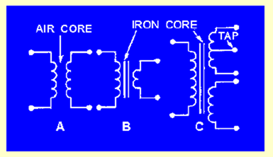
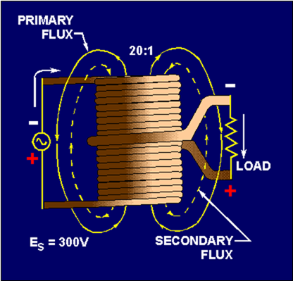
SCHEMATIC SYMBOLS FOR TRANSFORMERS Figure 5-7 shows typical schematic symbols for transformers. The symbol for an air-core transformer is shown in figure 5-7(A). Parts (B) and (C) show iron-core transformers. The bars between the coils are used to indicate an iron core. Frequently, additional connections are made to the transformer windings at points other than the ends of the windings. These additional connections are called TAPS. When a tap is connected to the center of the winding, it is called a CENTER TAP. Figure 5-7(C) shows the schematic representation of a center-tapped iron-core transformer. Figure 5-7. - Schematic symbols for various types of transformers. Q.7 Identify the below schematic symbols of transformers by labeling them in the blanks provided. HOW A TRANSFORMER WORKS Up to this point the chapter has presented the basics of the transformer including transformer action, the transformer's physical characteristics, and how the t...