Posts

Showing posts with the label DIRECT CURRENT GENERATORS

Summary of direct current generators
Image
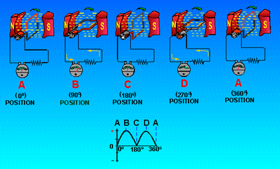
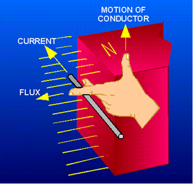
SUMMARY This chapter introduced you to the basic principles concerning direct current generators. The different types of dc generators and their characteristics were covered. The following information provides a summary of the major subjects of the chapter for your review. MAGNETIC INDUCTION takes place when a conductor is moved in a magnetic field in such a way that it cuts flux lines, and a voltage (emf) is induced in the conductor. THE LEFT-HAND RULE FOR GENERATORS states that when the thumb, forefinger, and middle finger of the left hand are extended at right angles to each other so that the thumb indicates the direction of movement of the conductor in the magnetic field, and the forefinger points in the direction of the flux lines (north to south), the middle finger shows the direction of induced emf in the conductor. AN ELEMENTARY GENERATOR consists of a single coil rotated in a magnetic field. It produces an ac voltage. A BASI...

Generator construction , voltage control , amplidynes and safety precautions

Image
GENERATOR CONSTRUCTION Figure 1-19, views A through E, shows the component parts of dc generators. Figure 1-20 shows the entire generator with the component parts installed. The cutaway drawing helps you to see the physical relationship of the components to each other. Figure 1-19. - Components of a dc generator. Figure 1-20. - Construction of a dc generator (cutaway drawing). VOLTAGE REGULATION The regulation of a generator refers to the VOLTAGE CHANGE that takes place when the load changes. It is usually expressed as the change in voltage from a no-load condition to a full-load condition, and is expressed as a percentage of full-load. It is expressed in the following formula: where EnL is the no-load terminal voltage and EfL is the full-load terminal voltage of the generator. For example, to calculate the percent of regulation of a generator with a no-load voltage of 462 volts and a full-load voltage of 440 volts Given: No...

Motor reaction in a generator , armature losses , hysteresis losses and field excitation

Image
MOTOR REACTION IN A GENERATOR When a generator delivers current to a load, the armature current creates a magnetic force that opposes the rotation of the armature. This is called MOTOR REACTION. A single armature conductor is represented in figure 1-10, view A. When the conductor is stationary, no voltage is generated and no current flows. Therefore, no force acts on the conductor. When the conductor is moved downward (fig. 1-10, view B) and the circuit is completed through an external load, current flows through the conductor in the direction indicated. This sets up lines of flux around the conductor in a clockwise direction. Figure 1-10. - Motor reaction in a generator. The interaction between the conductor field and the main field of the generator weakens the field above the conductor and strengthens the field below the conductor. The main field consists of lines that now act like stretched rubber bands. Thus, an upward reaction force is produced that acts in o...

Effects of adding additional coils and poles , electromagnetic poles and armature reaction

Image
EFFECTS OF ADDING ADDITIONAL COILS AND POLES The effects of additional coils may be illustrated by the addition of a second coil to the armature. The commutator must now be divided into four parts since there are four coil ends (see fig. 1-5).The coil is rotated in a clockwise direction from the position shown. The voltage induced in the white coil, DECREASES FOR THE NEXT 90° of rotation (from maximum to zero). The voltage induced in the black coil INCREASES from zero to maximum at the same time. Since there are four segments in the commutator, a new segment passes each brush every 90° instead of every 180°. This allows the brush to switch from the white coil to the black coil at the instant the voltages in the two coils are equal. The brush remains in contact with the black coil as its induced voltage increases to maximum, level B in the graph. It then decreases to level A, 90° later. At this point, the brush will contact the white coil again. Figure 1-5. - Effects of ad...

The elementary dc generator and Answers to questions

Image
THE ELEMENTARY DC GENERATOR A single-loop generator with each terminal connected to a segment of a two-segment metal ring is shown in figure 1-4. The two segments of the split metal ring are insulated from each other. This forms a simple COMMUTATOR. The commutator in a dc generator replaces the slip rings of the ac generator. This is the main difference in their construction. The commutator mechanically reverses the armature loop connections to the external circuit. This occurs at the same instant that the polarity of the voltage in the armature loop reverses. Through this process the commutator changes the generated ac voltage to a pulsating dc voltage as shown in the graph of figure 1-4. This action is known as commutation. Commutation is described in detail later in this chapter. Figure 1-4. - Effects of commutation. For the remainder of this discussion, refer to figure 1-4,parts A through D. This will help you in following the step-by-step description of the...

Direct current generators

Image
DIRECT CURRENT GENERATORS LEARNING OBJECTIVES Upon completion of the chapter you will be able to: State the principle by which generators convert mechanical energy to electrical energy. State the rule to be applied when you determine the direction of induced emf in a coil. State the purpose of slip rings. State the reason why no emf is induced in a rotating coil as it passes through a neutral plane. State what component causes a generator to produce direct current rather than alternating current. Identify the point at which the brush contact should change from one commutator segment to the next. State how field strength can be varied in a dc generator. Describe the cause of sparking between brushes and commutator. State what is meant by "armature reaction." State the purpose of int...