Posts

Showing posts with the label Wave-Generation and Wave-Shaping

Wave shaping: rl integrators and integrator waveform analysis.

Image
RL INTEGRATORS The RL circuit may also be used as an integrating circuit. An integrated waveform may be obtained from the series RL circuit by taking the output across the resistor. The characteristics of the inductor are such that at the first instant of time in which voltage is applied, current flow through the inductor is minimum and the voltage developed across it is maximum. Therefore, the value of the voltage drop across the series resistor at that first instant must be 0 volts because there is no current flow through it. As time passes, current begins to flow through the circuit and voltage develops across the resistor. Since the circuit has a long time constant, the voltage across the resistor does NOT respond to the rapid changes in voltage of the input square wave. Therefore, the conditions for integration in an RL circuit are a long time constant with the output taken across the resistor. These conditions are shown in figure 4-33. Q20. What characteristic of an RL circ...
Answers to question and summary of wave shaping

Image
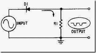
SUMMARY This chapter has presented information on wave shaping. The information that follows summarizes the important points of this chapter. A L IMITER is a device which limits or prevents some part of a waveform from exceeding a specified value. In a SERIE S LIMITER , the diode is in series with the output. It can limit either the negative or positive alternation of the input signal. In a SERIES- P O SI T IVE LIMITER , the diode is in series with the output which is taken across the resistor. It removes the positive alternation of the input signal. In a SERIES- P O SI T IVE LIMITER WITH BIAS, the bias potential will either aid or oppose the flow of current. When aiding forward bias, only a portion of the positive input pulse is removed. When the bias aids the reverse bias, all of the positive and a portion of the negative pulse is removed. The SERIES-NEGATIV E LIMITER limits the negative portion of the input pulse. The difference between a series-negative limiter and a ...

WAVE SHAPING:DIFFERENTIATORS AND COUNTERS.

Image
DIFFERENTIATORS DIFFERENTIATION is the direct opposite of integration. In the RC integrator, the output is taken from the capacitor. In the differentiator, the output is taken across the resistor. Likewise, this means that when the RL circuit is used as a differentiator, the differentiated output is taken across the inductor. An application of Kirchhoff's law shows the relationship between the waveforms across the resistor and capacitor in a series network. Since the sum of the voltage drops in a closed loop must equal the total applied voltage, the graphical sum of the voltage waveforms in a closed loop must equal the applied waveform. Figure 4-39 shows a differentiator circuit with the output taken across a variable resistor. Figure 4-39.—RC circuit as a differentiator. Short Time-Constant Differentiator With the variable resistor set at 1,000 ohms and the capacitor value of 0.01 microfarad, the time constant of the circuit is 10 microseconds. Since the input waveform...

Wave shaping: parallel limiters.

Image
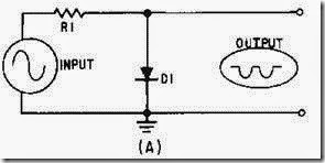
PARALLEL LIMITERS A PARALLEL-LIMITER circuit uses the same diode theory and voltage divider action as series limiters. A resistor and diode are connected in series with the input signal and the output signal is developed across the diode. The output is in parallel with the diode, hence the circuit name, parallel limiter. The parallel limiter can limit either the positive or negative alternation of the input signal. Recall that in the series limiter the output was developed while the diode was conducting. In the parallel limiter the output will develop when the diode is cut off. You should not try to memorize the outputs of these circuits; rather, you should study their actions and be able to figure them out. Parallel-Positive Limiter. The schematic diagram shown in figure 4-9, view (A), is a PARALLEL-POSITIVE LIMITER. The diode is in parallel with the output and only the positive half cycle of the input is limited. When the positive alternation of the input signal is applied to...

Wave shaping: nonsinusoidal voltages applied to an rc circuit and rc integrators.

Image
Nonsinusoidal Voltages Applied to an RC Circuit The harmonic content of a square wave must be complete to produce a pure square wave. If the harmonics of the square wave are not of the proper phase and amplitude relationships, the square wave will not be pure. The term PURE, as applied to square waves, means that the waveform must be perfectly square. Figure 4-28 shows a pure square wave that is applied to a series-resistive circuit. If the values of the two resistors are equal, the voltage developed across each resistor will be equal; that is, from one pure square-wave input, two pure square waves of a lower amplitude will be produced. The value of the resistors does not affect the phase or amplitude relationships of the harmonics contained within the square waves. This is true because the same opposition is offered by the resistors to all the harmonics presented. However, if the same square wave is applied to a series RC circuit, as shown in figure 4-29, the circuit action is not...